When considering how to mesh a geometry, decisions need to be made about the shape of elements to use to build that mesh. To describe the combination of different types of elements used for a particular mesh the term “mesh topology” is used.
For a 2D geometry, which is the best way to being explaining the decisions about mesh topology, there are two options:
Figure 3.2.1 illustrates how a 2D cross section of a horizontal pipe might be meshed using these two types of mesh element. On the top, the pipe is shown meshed using only triangular “tri” elements, and on the bottom meshed using only quadrilaterals “quad” elements. It should be noted that, although in this case all the elements are the same size and each of the edges of the elements are the same length (i.e. they are equilateral triangles and squares), this doesn't necessarily need to be the case.
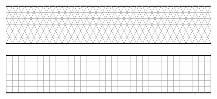
Figure 3.2.1 A 2D cross section of a pipe that has been meshed entirely with left) tris and right) quads.
There are 3D equivalents of tris and quads. These are:
The left of figure 3.2.2 shows a 3D tetrahedral “tet” element and the right shows a 3D hexahedral “hex” element. Again, it should be noted that, although in this case all the elements are the same size and each of the edges of the elements are the same length, this doesn't necessarily need to be the case.

Figure 3.2.2 left) A 3D tetrahedral “tet” element and right) A 3D hexahedral “hex” element.
With a domain, more than one element type can be used by joining different types of element to one another. For 2D meshes, this is quite straightforward, as both quad and tri elements are constructed with the same 1D line elements as their edges. However, joining tets to hexes is more complicated because the outer surfaces of tets are 3 sided triangles and the outer surfaces of hexes are 4 sided quadrilaterals.
Examples of joining 2D and 3D elements is shown in figure 3.2.3. To the left, tri and quad elements are easily connected together, sharing a line at their interface. To the right of figure 3.2.3, a tet element has been joined to the right hand face of the hex element. As the hex element has a quadrilateral face, and the tet has a triangular face, they do not share the same shape interface surface and do not completely join together.

Figure 3.2.3 Examples of joining different element shapes. Left) tri and quad elements can join with a common interface of a line. Right) tet and hex elements do not join together as they do not share a common face shape.
To join tets to hexes, two more elements are used in 3D meshes. These are:
These elements are shown in figure 3.2.4. To the left is a wedge and to the right is a pyramid.

Figure 3.2.4 Elements that can joing tets to hexes. Left) A wedge and right) A pyramid
As each of these elements contain both 3 and 4 sided shapes on their surface, they can be used to join tets to hexes. The tets are connected to the 3 sided faces and the hexes to the 4 sided faces.
An example of a pyramid being used to join a hex to tet is shown in figure 3.2.5. The base of the pyramid has 4 sides, and this joins to the upper face, which also has 4 sides, of the hex directly below. The top right face of the pyramid has 3 sides, and this joins to a tet, which also has 3 sides.

Figure 3.2.5 A pyramid element being used to join a hex to a tet. The 4 sided face of the pyramid joins to the hex and the 3 sided face of the pyramid joins to the tet.
All of this information about element shape and how elements are connected is very interesting, but so what? How does it help making decisions about a strategy to produce an optimum mesh topology for my simulation?
There is a lot of detail in the numerical methods employed solver and how this relates to the different types of elements that can be chosen for particular simulations. However there are some general principles that are broadly applicable that can help making decisions with little understanding of the details of the numerics. These are:
From this description, it would appear that the obvious choice would be to use quads or hex elements for everything. However, their major drawback is their ability to be applied to complex geometry. When a domain is a simple shape, such as rectangular or cuboid, it is obvious how this could be meshed with a structured mesh made of quads and tets. But when a geometry becomes slightly more complicated, algorithms in meshing software struggle to determine how to apply a structured mesh.
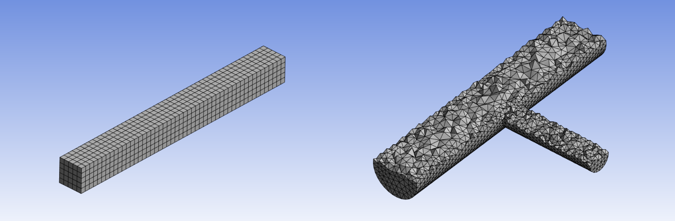
Figure 3.2.6 Illustrations of applications for hex and tet elements left) a simple cuboid shape well suited for a structured mesh of hexes right) a more complex shape requiring the use of tets to automatically generate a mesh.
Figure 3.2.6 shows 3D geometries that have been meshed. To the left is a cuboid that the meshing software generated in a few seconds based on a couple of parameters. It is able to detect the simple shape and fit a structured mesh into the domain. To the right is a geometry of two differently sized circular pipes connecting at right angles. Even for this relatively simple geometry, the meshing software was unable to automatically work out how to apply a structured mesh of hexes. Instead, as a CFD practitioner in a hurry, I opted for tets, which the software generated within a few seconds.
It is possible to apply structured hexes to more complicated geometries, but it takes significantly more manual effort to input the correct instructions for the meshing software to be able to generate the mesh. When considering the resources to invest in performing a CFD analysis, time is a significant factor. If accuracy and reducing compute resources are a priority for a particular application it may be worth investing the time to build a highly structured hex mesh. However, most commercial CFD users consider the time required to use them too great, and simply use automatic mesh generation to perform the job of discretizing the space.
Why do interfaces between joining elements need to be the same size? Why can’t the faces of neighbouring cells overlap? This would make joining cells much easier.
There is a way to join elements whose faces don’t line up. When a mesh like this is generated, it is called a “non-conformal mesh”. The left of figure 3.2.7 shows a 2D mesh made of hexes. In this case, all the faces of any one element line up with faces of the neighbouring elements. This is what is known as a “conformal” mesh. The right of figure 3.2.7, large elements are joined to small elements and tris are joined to quads and the shared faces between elements do not line up. One result of this type of meshing is “hanging nodes”, where a corner of one element is between the corners of a neighbouring element. In figure 3.2.7 the hanging nodes are identified with red circles.
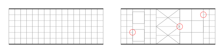
Figure 3.2.7 Comparison between left) a conformal mesh right) a non-conformal mesh, with some of the hanging nodes identified with a red circle.
The CFD solver runs a calculator based on conservation equations. For example, the conservation of mass. If mass flows out of an element through one of the surfaces, it is assumed all of that mass will enter the neighbouring cell through the shared interface. If there is not this 1 to 1 relationship connecting neighbouring cells, the calculation needs to consider the various fractions of mass that enter multiple connecting cells. This requires approximations and interpolations that add to the computational complexity of the problem, can produce less accurate results and may cause the solution to not converge (which means it doesn't reach an acceptably precise final answer). As such, automatic meshing software will not, by default, create non-conformal meshes unless explicitly instructed to do so. If they are created, these need to be set up correctly in the pre-processing software. Non conformal meshes should be avoided unless necessary.
There are situations where it is necessary to use a non-conformal mesh. For example, to simulate flow around solid parts that are moving relative to one another the mesh will need to move with the objects. A classic example of this is the simulation of flow from a turbine blade interacting with a stator.
There are alternatives to tri/tet and quad/hex meshes. Approaches using 3D elements with more than 6 faces is referred to as "polyhedral" meshing. This is beyond the scope of this material, but it can be independently researched to find out more if you are interested. All of the fundamental guiding principles in this teaching material, such as mesh density and refinement, will be equally applicable to polyhedral meshes.
« Previous Next »