The method CFD algorithms use to calcuate the flow parameters within the geometry requires the domain to be chopped up into small pieces. This process is called meshing. It may also be called “discretizing” (“discretising” in British English), because the space in the domain is being turned into discrete blocks.
Consider the reaction vessel to the left of figure 3.1.1, with two inlet streams entering from the bottom, mixing in the middle, and the outlet stream exiting at the top. In this left hand picture, the vessel is a continuous object, bounded by the outside line that separates the flow domain from the surroundings. The job of meshing this continuous object is to divide the space into a series of connected pieces, as shown to the right of figure 3.1.1.
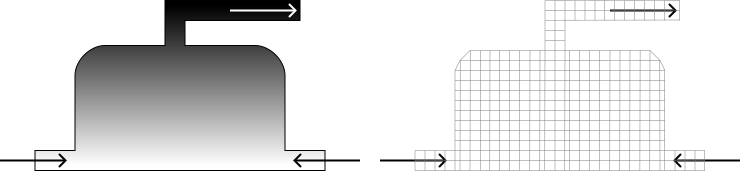
Fig 3.1.1 left) A 2D illustration of a reaction vessel right) the same reaction vessel with the space discretized by a mesh
The elements of a mesh are “discrete” when you do not consider any variation within the boundary. When the CFD solver calculates the various physical parameters such as velocity and pressure, it will only hold one pieces of data to represent each variable it is calculating in each cell. For example, if it is calculating pressure, it won’t calculate or hold information about how the pressure is different at the top or bottom or middle of the element, it will simply have one value for pressure that is the single value for the whole of that element.
As an example, consider the velocity distribution shown in figure 3.1.2, with a scale of red representing fast and blue representing slow. On the left is a representation of the velocity distribution you would expect in a real, physical system. There is a continuous variation of velocity spread across the space where the is fluid. The image to the right of figure 3.1.2 shows how the data is stored when a mesh is used. Each discrete elements holds a single value of velocity that represents the entire are covered by that element.
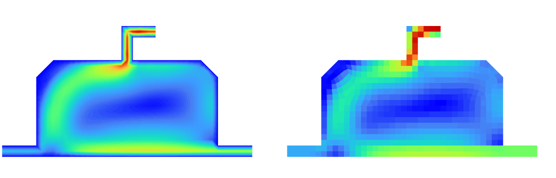
Fig 3.1.2 CFD calculation of velocity distributed in a reaction vessel left) a continuous distribution of the value of velocity right) discrete values of velocity in each cell
As shown in figure 3.1.2, the CFD solver will discretize the fluid flow equations and do this based on the discretization of the mesh. At the meshing stage of the overall CFD workflow, the physics that will be applied to the mesh is unknow to the computer, so it is only the space that is being chopped into elements. That being said, to make decision about how the space is meshed, understanding of the physics that will be applied downstream n the workflow need to be considered.
When reading about CFD, you may see the term “grid” used in place of “mesh”. The two terms can be used interchangeably, although “grid” tends to be used when the smaller pieces that make up a mesh are regularly ordered, like the grid of a chess board. The term mesh is more widely applicable and so will be used in this course.
Each piece is an element. The term cell can also be used. While there is a subtle difference between a cell and an element, during the meshings stages of a CFD analysis the terms can be used interchangeably. In this course, I’ll stick to the term element.
« Previous Next »