In this tutorial, we will gain a familiarisation with the software DesignModeler, which is one of the tools provided in Ansys Workbench for creating geometry. We will introduce the window layout of DesignModeler, how to work in different planes in the x, y, and z coordinate space, the creation of 2D sketches that can be extruded into 3D objects, and how to change the dimensions of geometrical elements. We will also introduce the idea of “frozen” material and tools for selecting different parts of a geometry. These concepts will be presented by following step to create simple shape – a cylindrical pipe. The tutorial is not designed to be exhaustive. It is simply a familiarization exercise to allow you to become acquainted with the interface, workflow and some of the functions of DesignModeler.
Time to complete: 15 minutes.
Pre-requisite tutorials: Ansys Workbench Familiarisation
Ansys Workbench has a number of different geometry creation tools. In certain versions, DesignModeler is the default and in others it is not. When you create a Geometry component in the workbench, you can select which geometry creation software to use from the options in version you have installed. DesignModeler is the oldest tool in the Ansys suite, so it is available on all versions (at the time of writing) but is also the least modern in terms of user experience and capability.
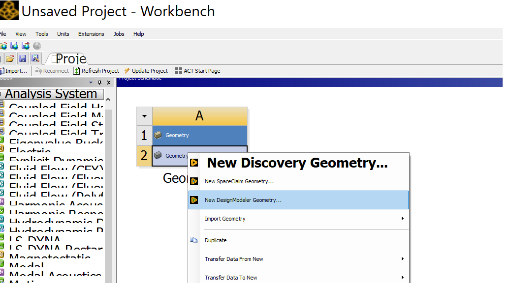
Step 1:Open Ansys Workbench and drag a Geometry component system onto the project schematic (the instructions for performing these tasks are on the Ansys Workbench Familiarisation Tutorial. On the 2nd row of the Geometry component, right click and select New DesignModeler Geometry... . The DesignModeler software should open in a new window.
As with most of the Ansys software, DesignModeler consists of a series of panels inside the main window. These can be pinned, repositioned and docked to the user’s preferences. In this tutorial, we will use the default layout. If the default layout is lost, either by mistake or by experimenting with how it can be adjusted, it can be restored from with “View”, “Windows”, “Reset Layout” options from the top menu.
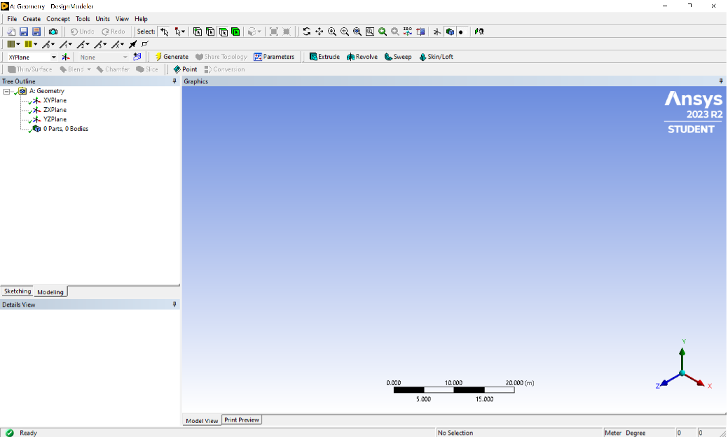
The DesignModeler interface consists of the following panels:
DesignModeler allows you to create sketches and bodies.
At the bottom of the Graphics window, there is black ruler in the centre and an XYZ triad to the right. These items help with orientation and scale. Before any geometry is created, there is no way to know the extent the Graphics window is zoomed in. The ruler is very helpful in this scenario.
Step 2:We will be building a circular
In order to build a sketch, a 2D plane needs to be selected. A user defined plane can be created, but three are provided by default. These are XY, ZX and YZ
Congratulations on reaching the end of this tutorial. In summary, you have learned to: