In this tutorial, we will gain familiarity with Ansys "Workbench" software. We will cover how to open the software, navigating the various windows within its interface and understand how to operate a few of the functions for creating a CFD simulation. We will also show how to open, save, and copy a Workbench file.
Time to complete: 10 minutes.
Pre-requisite tutorials: None
If you are using a University of Sheffield PC, Ansys workbench should already be installed. It can be opened by typing into the search bar (which, by default, this is next to the windows icon in the bottom left of the screen) the word "workbench" and selecting the Ansys Workbench Software. An example of opening Workbench from the windows search bar is shown below.
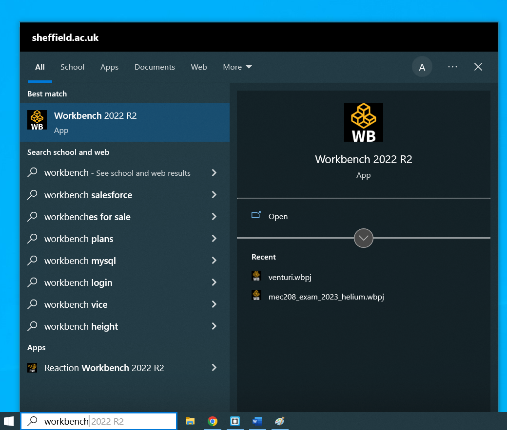
Different versions may appear when searching for Workbench. In the case above, the version is 2022 R2. This is the second revision (R2) in the year 2022. You may see a different version number depending on what is installed on the particular PC you are using.
If you are using your own PC, you will need to install the Ansys software. A student version of the Ansys software is provided by Ansys for free, and can be found here. Installing the software is quite demanding and can only be run on a reasonably specified PC. It typically requires many gigabytes of free space and can take a long time to install. It is convenient to have a copy on your own computer, but if you are unable to install it then you can use one of the PCs provided by the University.
Step 1: Type workbench into the windows search bar and launch the Ansys Workbench software. Note down the version number.
Workbench is not a simulation tool. Instead, it is software that provides access to, and keeps track of the interactions between, a suite simulation tools.
The company Ansys has a many individual software tools, each one performing a specific function. In typical engineering simulation workflows, users will need to use a combination of these tools. For example, for a typical CFD analysis, a user may want to generate geometry, apply a mesh, pre-process the physics of the simulation and analyse the results. Using Ansys, all these functions are performed using individual pieces of software. Workbench helps keep track of the overall workflow and different tools being used.
If you are performing complex simulations, for example coupling together tools modelling fluid flow, structural mechanics and electromagnetism, the interoperation between each of these pieces of software can be managed through workbench. Another example of the value of the workbench is keeping track of multiple scenarios of using the same software. For example, if you wanted to generate and compare multiple instances of different meshes, each derived from a single geometry.
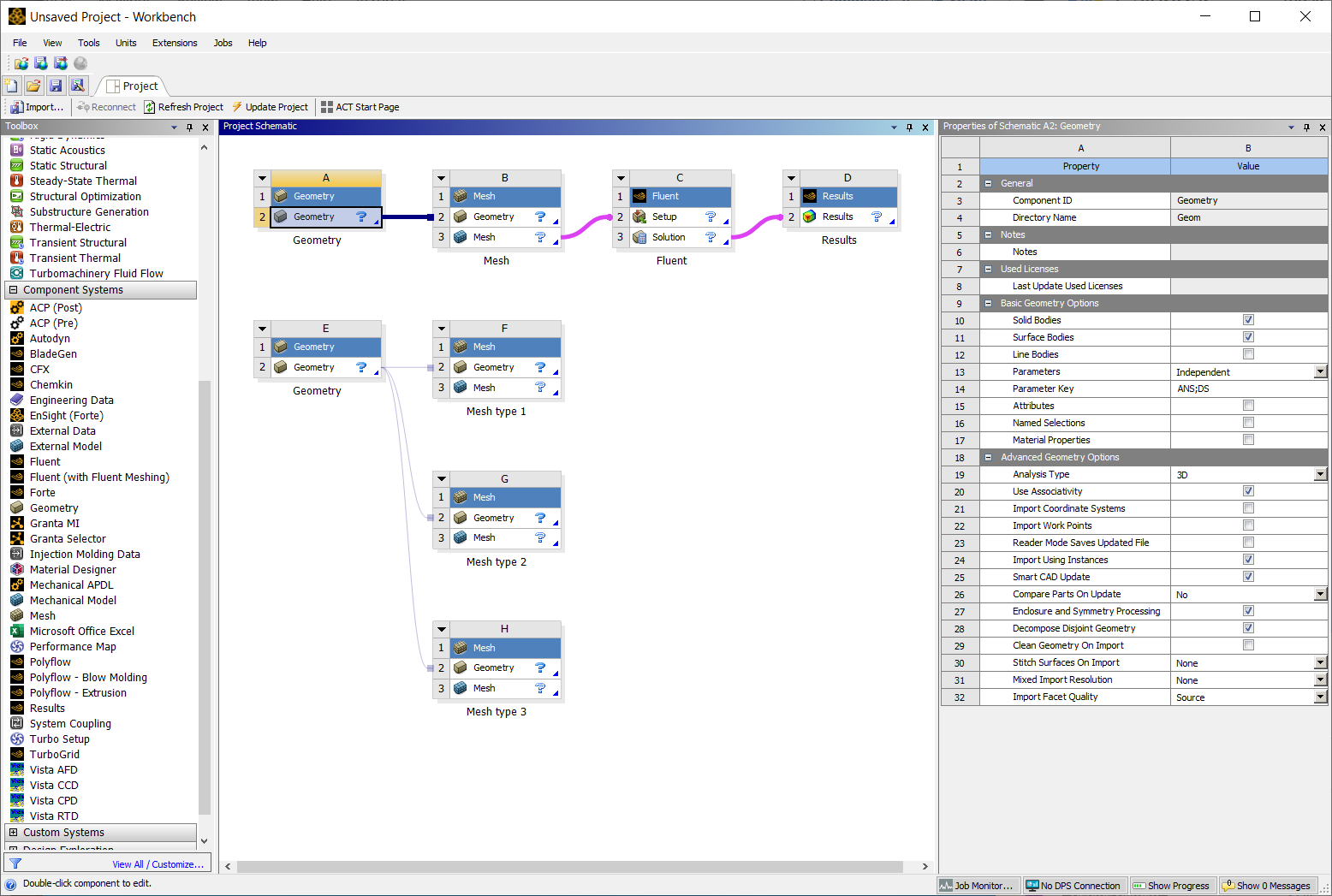
An example of the workbench window is show above. The layout of the window is very similar to most pieces of engineering software. There is a top menu bar, consisting of options such as File, View, Tools...etc. To the left is the "Toolbox" (the word "Toolbox" appears in the grey header of the pane to the left-hand side), which contains a menu of "Analysis Systems" and "Component System", discussed below. In the centre is the "Project Schematic", which is where the different pieces of software within that Ansys suite that you wish to use in your simulation are placed. To the right, a properties window can be opened or closed.
Step 2: Ensure you know how to toggle the properties window on the left on and off. From the View menu at the top of Workbench, select Properties. Ensure the properties window remains open.
In the example above, a number of "systems" have been placed onto the Project Schematic. At the top of the Project Schematic is an example of a typical CFD workflow. System A (which can be identified with the letter in the header of the system) is a Geometry system, which would open with the software "DesignModeler", system B is a Mesh system, which would open with the Meshing software, system C is a pre-processing and calculation system, which would open with the "Fluent" software, and system D is a Results system, which would open with software "CFD-Post".
In the left hand toolbox menu there are a number of options. The two of interest are "Analysis Systems" and "Component Systems". The menu options can be expanded or collapsed using the little + and - symbols next to the "Analysis Systems" and "Component Systems" titles. Expanding the Analysis Systems tile shows items such as "Coupled Field Harmonic" and "Fluids Flow (Fluent)". Expanding the Components Systems title shows items such as "ACP (Post)", "Fluent" or "Geometry".
It is easier to start by explaining "Component System". Component systems are individual pieces of software that do specific jobs. For example, software to build a geometry, mesh a geometry or analyse results. In the picture of the workbench above, all the systems in the Project Schematic (systems A to H) are components. Components can be connected in a variety of ways, depending on the complexity of your simulation.
An "Analysis System" is a pre-determined combination of Component Systems. For a commonly used combinations of components, an Analysis System can be selected. It eliminates the need to select and connect individual components. In the example workbench above, systems A, B, C and D in the Project Schematic are single Geometry, Mesh, Fluent and Results component systems, sequentially connected together. As this is a common workflow for a CFD analysis, the same results can have been achieved by using the "Fluid Flow (Fluent)" Analysis system.
The advantage of Analysis Systems over Component systems is they are quicker and easier to implement if the combination of systems you need to use is available as an Analysis system. If your workflow is more complex, as is the case of the three meshes (systems F, G and H) from the single geometry (system E) show at the bottom of the Project Schematic in the workbench example above, it will need to be constructed using individual component systems.
In these steps, we will add a typical CFD simulation workflow Analysis system to the Project Schematic.
Step 3: Ensure the Analysis Systems menu in the Toolbox is expanded (with the + icon, if a – symbol is shown it is already expanded) to allow all the Analysis Systems to be displayed. Find Fluid Flow (Fluent).
Step 4: Left click and hold Fluid Flow (Fluent). A green box will appear in the Project Schematic. With the left mouse button held, drag the Fluid Flow (Fluent) analysis system into the green box. The green box will go red.
Step 5: Release the left mouse button over the red box and the Fluid Flow (Fluent) Analysis system will be placed onto the Project Schematic as system "A".
In the next steps, we will add a Geometry component system to the Project Schematic. We will also add a Mesh system. We will do this in such as way that the Geometry and Mesh are connected.
Step 6: Expand the Components Systems menu in the Toolbox is and find Geometry.
Step 7:As before, drag the Geometry system into the green box of the Project Schematic. Release the Geometry system when the green box goes red. System B has been created.
Step 8: Find the Mesh in the Components System menu of the Toolbox.
Step 9: Take care with this bit. Drag the Mesh system from the Components System Toolbox on top of the 2nd Row of the Geometry system B. The row should go red when the system is hovering over the correct location. Release the Mesh system on top of the Geometry system and a new Mesh component, named C, will appear on the Project Schematic. The Geometry and Mesh systems should be linked with a line.
The final step in this section is to provide instruction for deleting systems from the Project Schematic. If you have placed something on the Project Schematic in error or have made an error inside the software and want to start again from the beginning (which is often quicker than debugging an issues), then you will want to delete the system. As we will not be using the systems placed on the Project Schematic any further in this tutorial, they can be deleted without compromising any further work.
Step 10: On any of the systems on the Projects Schematic, A, B or C, locate the down arrow, on the left of the title line. Click this down arrow to expand menu options for that system then click Delete.
Step 11: A warning, may appear about the loss of data as a result of deleting the system. ClickOK.
The workbench interface has several windows, such as the Toolbox, Project Schematic and Properties window, that can be arranged according to the user's preference. Windows can be docked, pinned, or closed using the icons to the left of the title bar at the top of the window. A common problem experienced by new users is losing the original window layout. This can cause a problem with finding the function you need, especially if you are following tutorial instructions that expect a particular layout. The original, default layout can be reset at any point.
Step 12: Use the close (X) button to close any of the windows, such as the Toolbox, Project Schematic or Properties window. If you want to be more adventurous, you could try resizing, unpinning or docking windows, using the icons in the window's title bars. Do not close the Workbench window, as this will close the Workbench software. If you do, you can relaunch the Workbench software as descried above.
Step 13: Restore the default layout: From the View menu at the top, select Reset Workspace. This should bring back the Toolbox and Project Schematic to their original, default layout.
Remember, the Workbench is a system to keep track of several other software tools, each one saving files in a particular format. For example, the Geometry software will save files in a particular format and the Mesher will save files in a different format. To help manage the number of files and their interconnections, Ansys Workbench defines a "project".
Step 14: From the Workbench top menu, click File and select Save. As this is the first time you will have saved this project, a window will appear inviting you to select a location on your computer to save your file and input a name. In this example, I will use the filename "test_project" and save it to my desktop, but you can chose any name and location where you have write access.
Step 15: Use a file browser (for example, "File Explorer" in windows) to locate where the file was saved. Notice there is 1 file and two folders associated with this save.
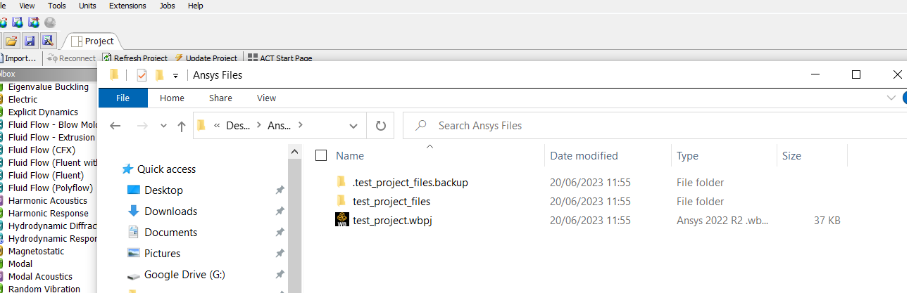
In this image above, you can see the saved file and the two folders. In this set up of the file browser, hidden files and file extension are visible. This may not be the case on the computer you are using if these properties haven't been enabled, but this will not matter for the purposes of understand the file handling.
The file "test_project.wbpj" is the workbench project file. This contains no data from any of the systems within the Project Schematic, but only data about how the Project Schematic is configured. All the data from the systems inside the Project Schematic are saved inside the "test_project_files" folder. The important aspect to remember is that, if you are transferring data from one location to another - for example you want to save you work to a USB stick, you need to save both the project file ("test_project.wbpj" in this case) AND the project folder ("test_project_files" in this case).
In the tutorials associated with this course, pre-prepared Ansys Workbench files will need to be downloaded to your computer. Because the files provided will need to contain both the workbench project (.wbpj) file and the directory, these will be zipped. They will need to be unzipped and you will need to know their location within your computer's file system where. How to use a computer's operating systems is beyond the scope of this course, but there is plenty of help on the web or Chat GPT for how to use Microsoft Windows. For unzipping files, Microsoft provides some help here.
The third item, the ".test_project_files.backup" folder, is a hidden folder that is created while the workbench software is open. This folder should disappear when you close Ansys Workbench. It keeps a live update of changes that are being made while using the software and can be used for recovery in the event of a system crash. However, this isn't an easy process and one that doesn't always work. The Ansys Workbench software will not save automatically and allow you to roll back changes that were made in error. It is worth saving regularly, using the save option in the software, especially when moving between different pieces of software. It is also worth saving different versions as your work progress, so it is easy to roll back to an earlier point if you have made an error you cannot unpick.
Finally, it is worth noting that when you are inside one of the components software packages, such as the Geometry or Meshing software, there is an option to "Save Project". When saving a "project", all the systems inside the Project Schematic will be saved at the same time. For example, if the Geometry and Meshing software is on the Project Schematic you can click "Save Project" in the Meshing software and it will automatically save any edits from the Meshing software and any that have been made previously inside the Geometry software.
In the final step of this tutorial, we will ensure understanding and competency in downloading and opening pre-prepared Workbench project files. You will need to access space on your computer where you can save files, and the use of the file systems software will be dependent on what computer and operating system you are using.
Step 16: Download the file AnsysExample.zip to a place on the computer you are using that has write access. Navigate to the file and unzip the contents.
Step 17: With Workbench open, from the top file menu select File and Open. Navigate to where you upzipped the download file and locate the file "AnsysExample.wbpj" (the .wpbj extension may not be showing if you operating system is set to hide file extensions). Click Open. If you are prompted about saving the project you are currently working on, click No, as we do not need the current project any further in the tutorial (or save it somewhere if you wish).
Step 18: Depending on what version of Ansys Workbench you are running, there may be a warning about forwards compatibility. This can be ignored (although be aware of that Ansys Workbench is not backward compatible, and if you don't understand what that means, it can be looked up on google/chatGPT). After clicking through any warning boxes, the pre-prepared Ansys Workbench project should be displayed in the Project Schematic.
Congratulations on reaching the end of this tutorial. In summary, you have learned to: